Step 1
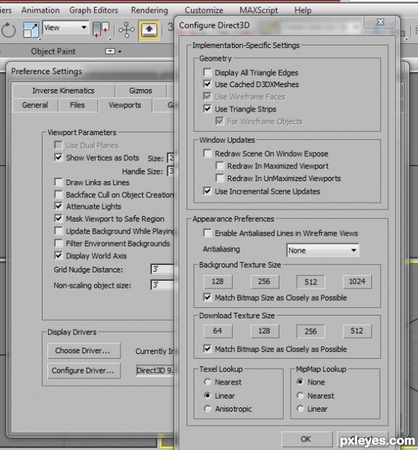
This tutorial can be followed by anyone using 3ds Max 208 or later. I am using 3ds Max 2012 so the screen shots may be a little different. However the general guidelines can be followed with almost any version of 3ds Max.In versions earlier then 2011 you may need to increase the image sharpness in your viewport display. To do this, before doing any work go to customize, then preferences and click on viewport tab.
Next click on configure driver and then make sure background texture size and match bitmap size as closely as possible are checked. You will have to reset your 3ds max interface by clicking on file then reset. Now you should see your textures in the viewport crisp.
Step 2
To start it is a good idea to search the web and download as many images of the real thing you are going to model to use as references.For our model we are going to search the internet for Eurocopter AS350. Google images is a great place to start, however an even better place is a website dedicated to providing free aircraft photos.
www.airliners.net Also we will need a blueprint to follow, we can get these at www.the-blueprints.com
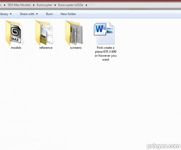
When you have your reference images and blueprints place them into folders so you can nicely manage them while you model as shown below.
Step 3
So to start create a plane 670 X 690 or however you want, with 1 height and width segment. Next take your blue print that you downloaded from the-blueprints.com and apply it to your plane. You can do this by going to your material editor and picking bitmap from the map list and then chose your blue print.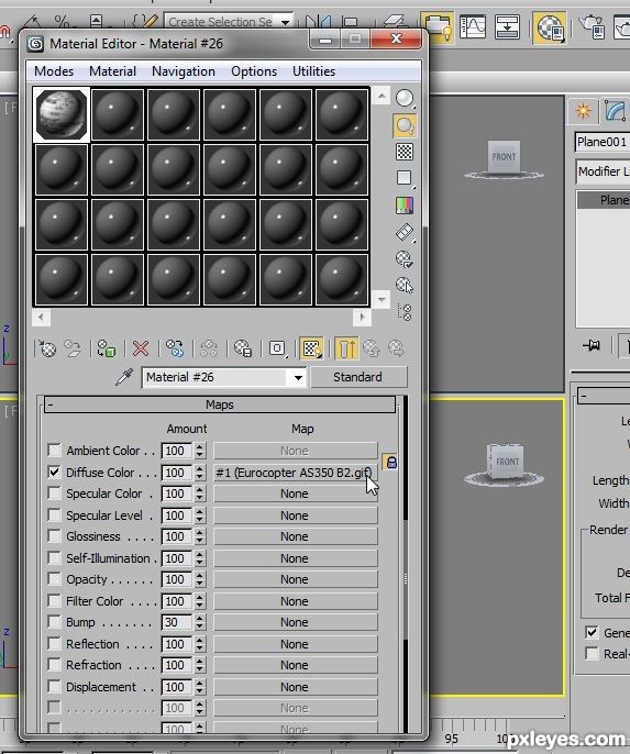
Step 4
Next we are going to cut our blueprint up, to do this we need to convert our blueprint to an editable poly object. You can either right click or select convert to editable poly or you can apply it in the modifier stack. I like to use the modifier stack because if I make a mistake I can always delete the modifier.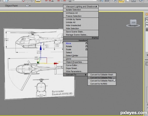
Step 5
Next activate your edge mode and select both sides of your plane, as seen in the image. Next click connect and create a new line across your image.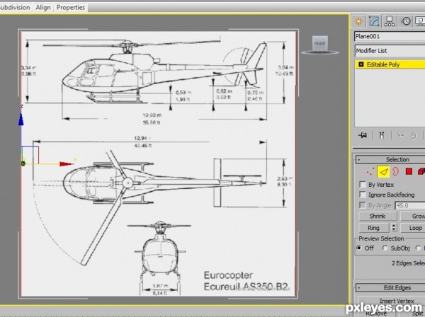
Step 6
Continue to do this until you have completely sliced up your image so it looks like the image below.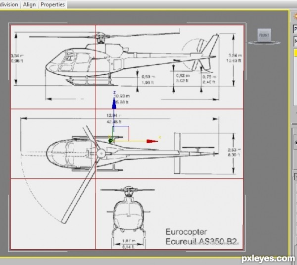
Step 7
After you have sliced up your image activate polygon mode and select each part of your newly sliced plane and detach them so you have three different panels like this.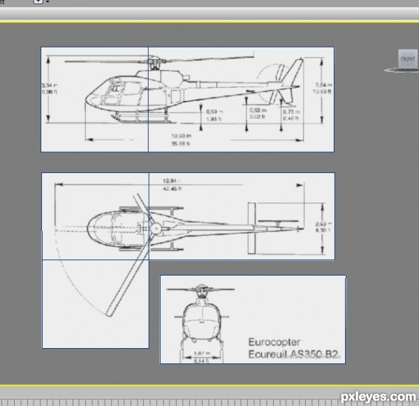
Step 8
Next arrange them according to each view. Front, Side and Top.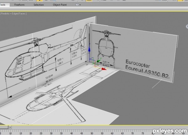
Step 9
One last thing we need to do before we start modeling, select all the planes, then right click and chose properties than uncheck frozen in gray and press OK. Next right click and chose Freeze selection, that’s it, we are now ready to model.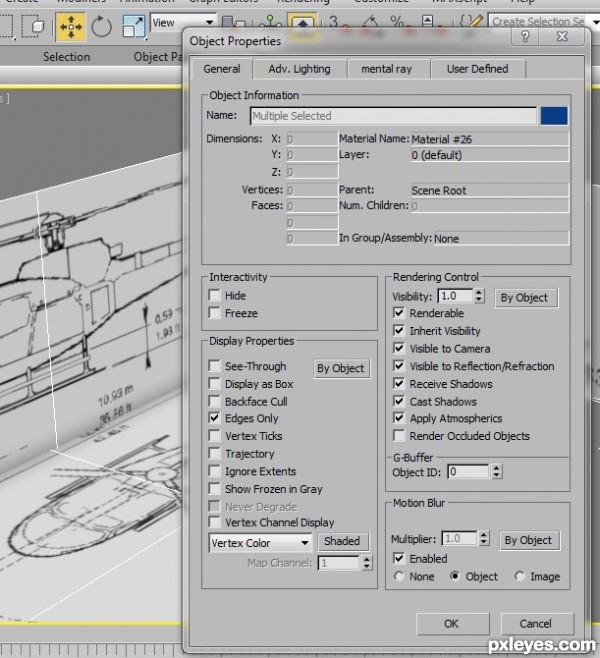
Step 10
I like to start out by using a plane to model with, so create a plane in the side view and convert it to an editable poly object. You can also apply a generic texture to it so you have more control, I am going to choose a nice light blue texture.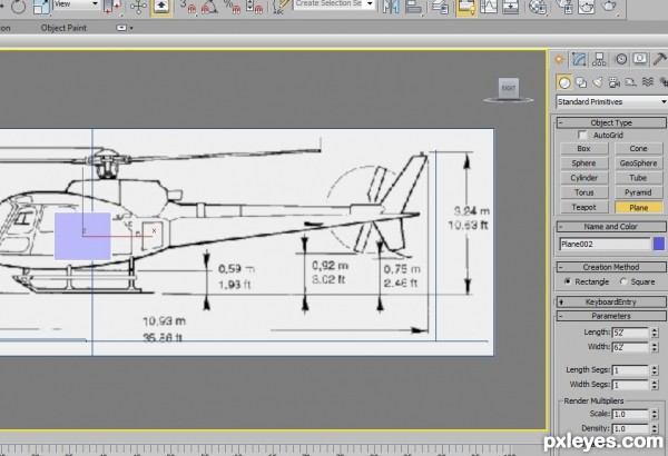
Step 11
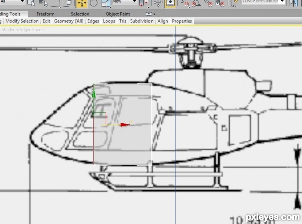
Next if you hold down (ALT) + (X) your model becomes see-through. Do it again and your model turns back to its original state. This is very useful when modeling o we can see our blueprint as we work.Start by activating edge mode and then selecting an edge, next while holding down the SHIFT key drag out. This extrudes the edge as you can see here.
Step 12
Continue to drag out edges until the full side of your aircraft is complete, except the tail part. We will work on that separately. You should have something like this when you are finished.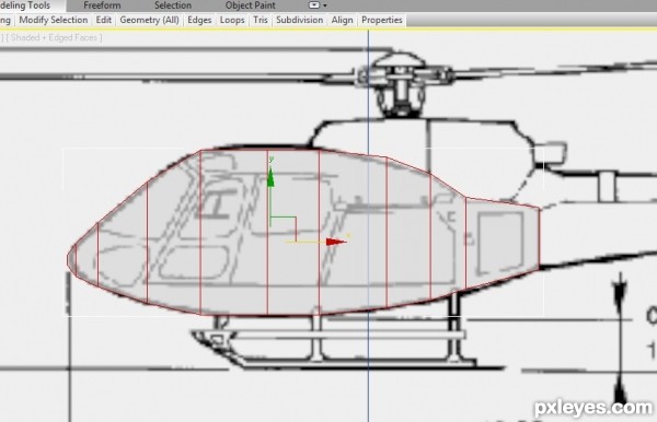
Step 13
Next go to the top view and activate vertex mode, select any vertex that is not in line with your blueprint and move it in so it lines up, as seen here.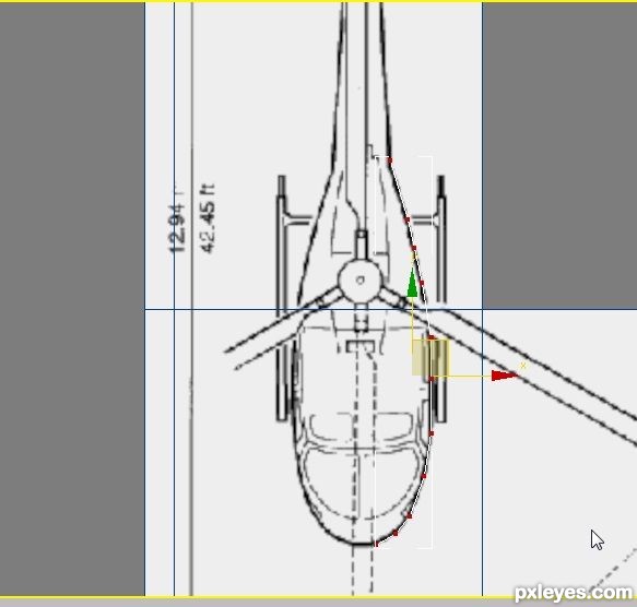
Step 14
Next we can take the top edge and extrude it up and in, use all three viewports to work your model so you get something like this.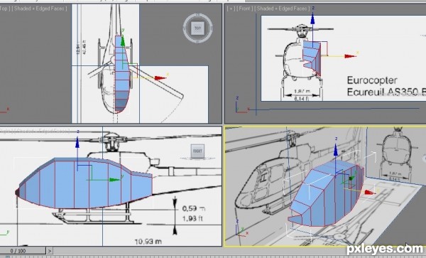
Step 15
There is an open part in the front, we can close this also by selecting both the end vertexes and clicking on collapse in your modifier stack. We can do the same edge extrude for the bottom of our aircraft.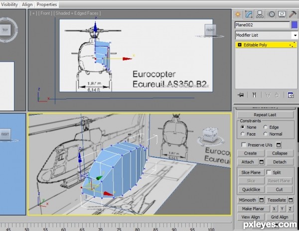
Step 16
Next lets ad a symmetry modifier to our model so we can see the other side of our aircraft update as we work on one side of our model. This way we get to see what changes will look like to the whole model without modeling the other side. You can apply the symmetry from the modifier menu as seen here.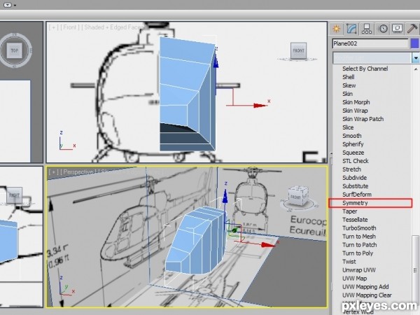
Step 17
Next lets work on giving our model more shape. Activate edge mode and start creating more edges by selecting the cut tool and cutting in more lines to help give our model more depth. These are the new edges I created.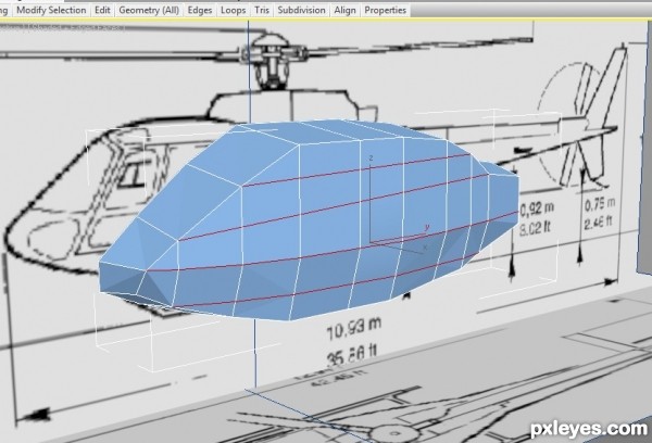
Step 18
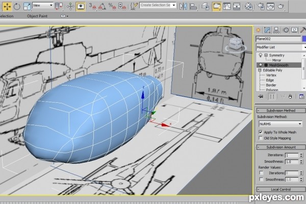
Next select your vertex mode and start moving in more vertexes so your model conforms to your blueprint better. Next let’s apply a mesh smooth modifier to our model just under our symmetry modifier, so we can see what our model will look like smoothed.Your model should look something like this with the modifier applied.
Step 19
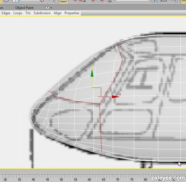
Now let’s focus on the windshield part of our aircraft, continue to make new cuts and move vertexes around until your cockpit area looks more in line with your blueprint. When you are finished you should get something like this.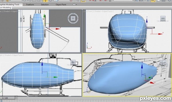
Step 20
Next let’s start creating the tail and tail fin. Activate edge mode and start extruding the back end until you get a nice tail shape, remember to use all three views and to activate vertex mode when you are done and move your vertexes in place, this is what I created.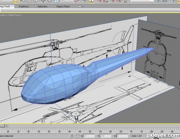
Step 21
Next to create the tail fin, we will need to make two slices here.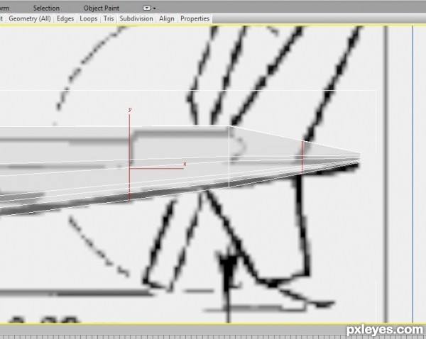
Step 22
Next select these faces in polygon mode and extrude them out, then activate vertex mode and move your vertexes in place.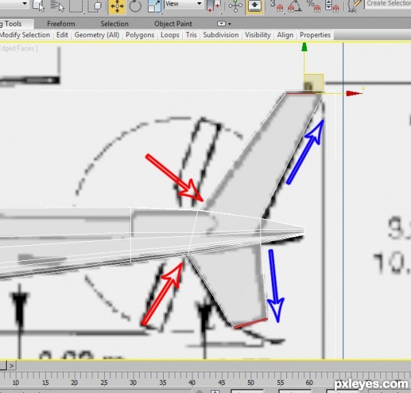
Step 23
Always remember to delete the inside of your aircraft model when extruding, because when you use symmetry you automatically weld your model together, so if there are any polygons inside your model, you will get a bad look when using mesh smooth.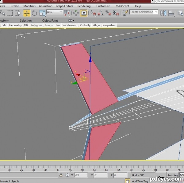
Step 24
Next to make our tail stay in shape when we apply our mesh smooth, we need to give our tail shape some extra lines. So select both tail edges by dragging a selection box around both tail edges and apply a connection, by clicking on connect, use 2 segments and a pinch of 90.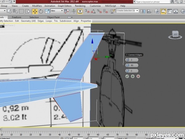
Step 25
Next we can work on building the engine on top, start by activating polygon mode and selecting these faces.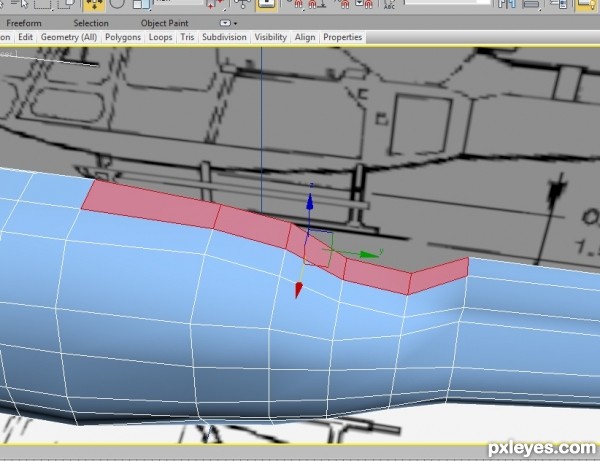
Step 26
Next delete the polygons and then select edge mode and select all the edges that were deleted, then hold down SHIFT and extrude up following the blueprint.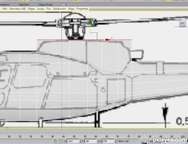
Step 27
Add more lines and move vertexes around until you get something like this.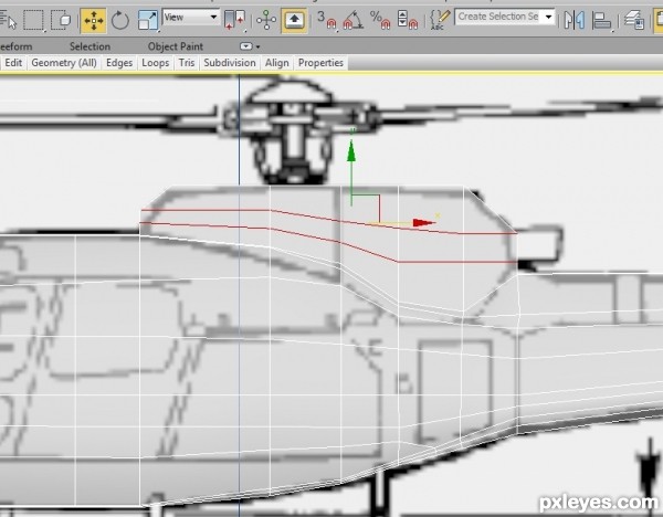
Step 28
Next we need to close the top, so select these lines and extrude in. Remember to collapse any lose vertexes.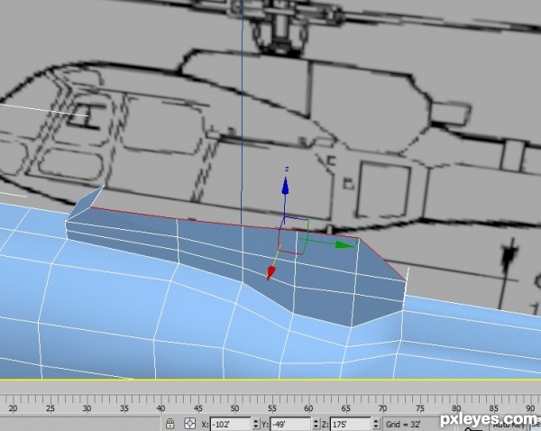
Step 29
Next use the inset command in polygon mode and inset your back selection to 0.5 as seen here. Next use your scale command and scale in a small amount and then delete the selection.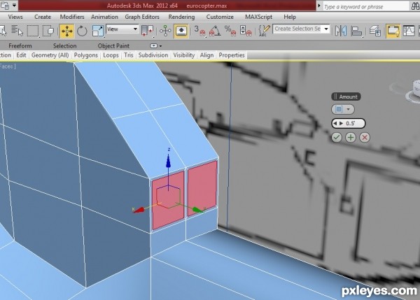
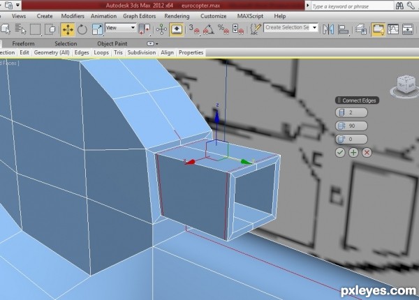
Step 30
Next select edges and extrude out to create the exhausts tube. Remember to close any lose vertexes or lose edges, when you are done you should have something like this.To make our tube hold its shape, place two new lines around it by selecting the edges around the tube and then pressing connect, give it 2 segments and a pinch of 90. I also extruded the inside a small bit to make it more tube like.
Step 31
Here is what it looks like with mesh smooth applied.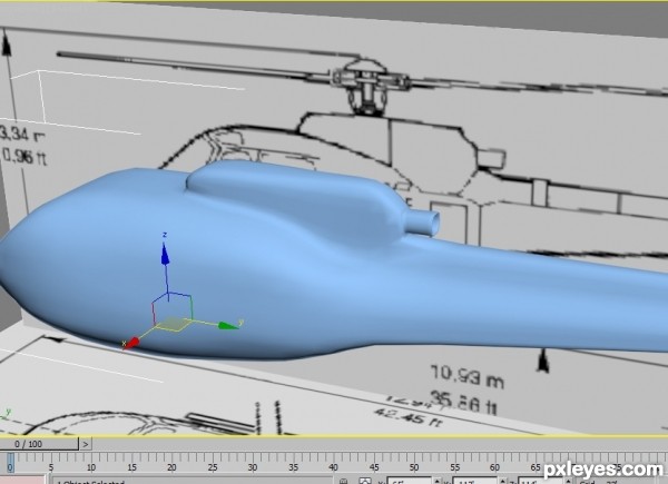
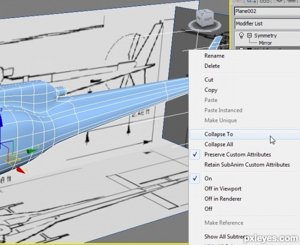
Step 32
Now that we have the basic shape, it is time we start to do more detail work. Before we go any further, save your model and then save another copy of your model so that if anything goes wrong in the modeling process you can always load the last saved version to work from.So to start off we need to convert our model into a mesh smoothed model. Do this by right clicking on your mesh smooth modifier when it is active and choosing collapse too.
Step 33
Now that our model is mesh smoothed we can work on the windshields and doors.Let’s start by bringing up the side view, then turning our model see-through by pressing ALT X, then chose either edge mode or vertex mode and use the CUT tool to start cutting a line following the shape of the windshield like this.
Step 34
Next activate polygon mode and select your new window, as seen here with symmetry applied.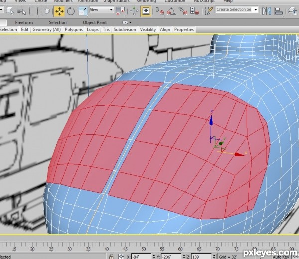
Step 35
Next we can inset and extrude in so we get the windows.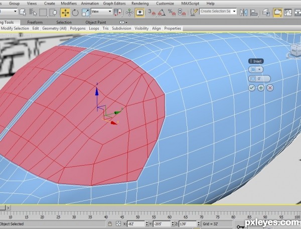
Step 36
Inset to 0.5 and extrude to -0.5 this will give us a nice window shape.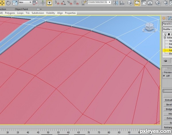
Step 37
A good idea now is to click on detach and chose detach to element. This way you can select the whole window just by clicking on it when in element mode.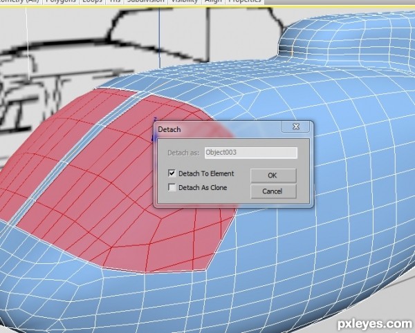
Step 38
Let’s choose a different color for our windows so we know what they are as we model. I chose a dark blue with opacity of 60.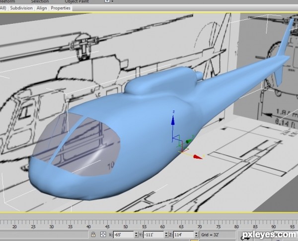
Step 39
Do the same process to all the windows on your aircraft and you can also cut the doors, but only cut the lines for the doors do not inset or extrude them. You should get something like this when you are finished.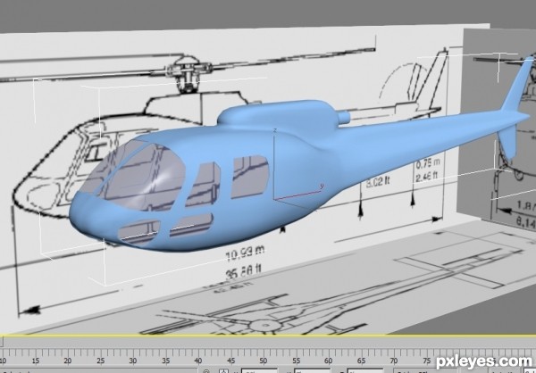
Step 40
Next if you have not yet cut out your doors, do so now, you should get something like this when you are complete. Select each door using your polygon tool and chose detach to element, we will work on the doors more later.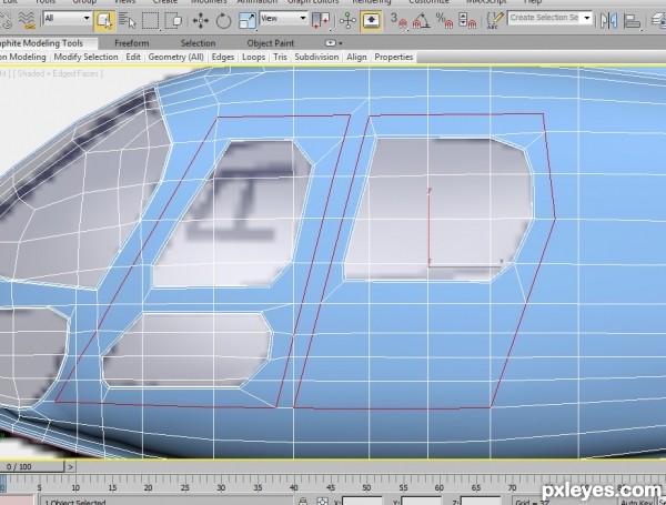
Step 41
Color your doors a different color so you can see them while modeling.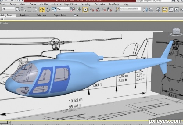
Step 42
Next let’s build the chopper blade on top, start by creating a cylinder in the top view and position it according to our blueprint, I used a radius of 4, height of 25, 1 segment and sides 20. When you are ready convert it to editable poly object.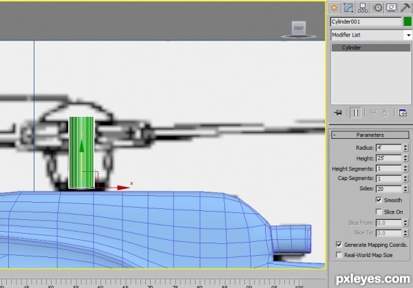
Step 43
We need to create some new lines, so here is what I did.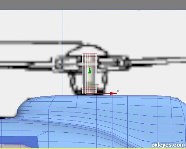
Step 44
Next select your polygons around the new tube you created and extrude them out like this, use local normal and an amount of 9.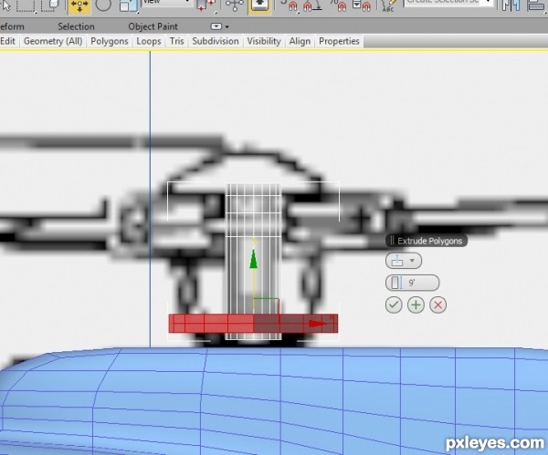
Step 45
Continue doing this until you get something like this.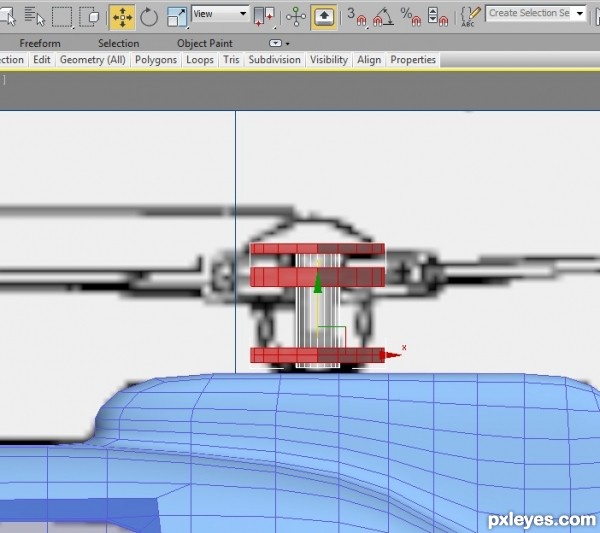
Step 46
Next we can shape our new extruded parts a little by moving vertexes and by creating some new lines, like this.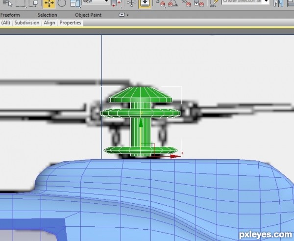
Step 47
So now let’s create our blades. All we need to do is create a box with these dimensions, length 225, with 14, height 3, and segments of 1.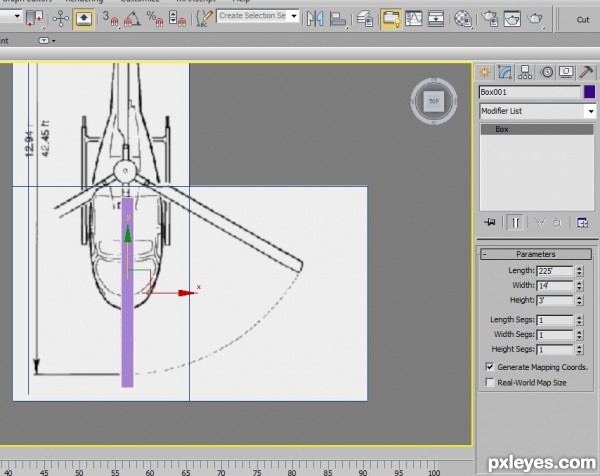
Step 48
Convert to editable poly, and start cutting and moving some vertices, also we can extrude the back end, this is what I did.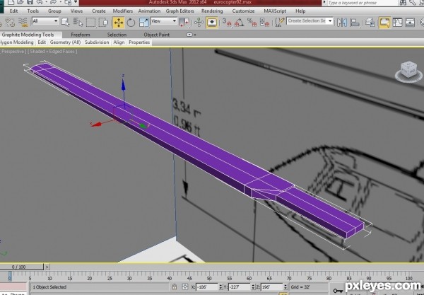
Step 49
Next make 3 copies and rotate them so they line up with the top blueprints like this. You can easily rotate them if you change the axes by going to the hierarchy tab and clicking on affect pivot only, then move your pivot point to the center of your rotor disk.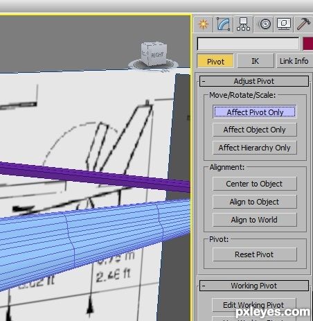
Step 50
Make 3 copies and rotate them so they line up with the top blueprints.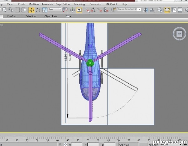
Step 51
In this next image I attached all three blades with the base and gave them a dark gray color.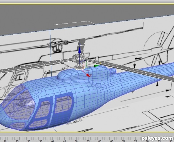
Step 52
For modeling the back tail blades it is the same process. When you are finished you will have something like this.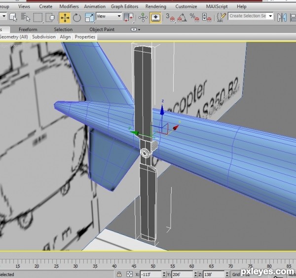
Step 53
Next we can create the side tail boom to stabilize the back of the aircraft. Activate polygon mode and select these polygons.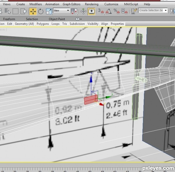
Step 54
Extrude them out and move vertexes around so you get something like this.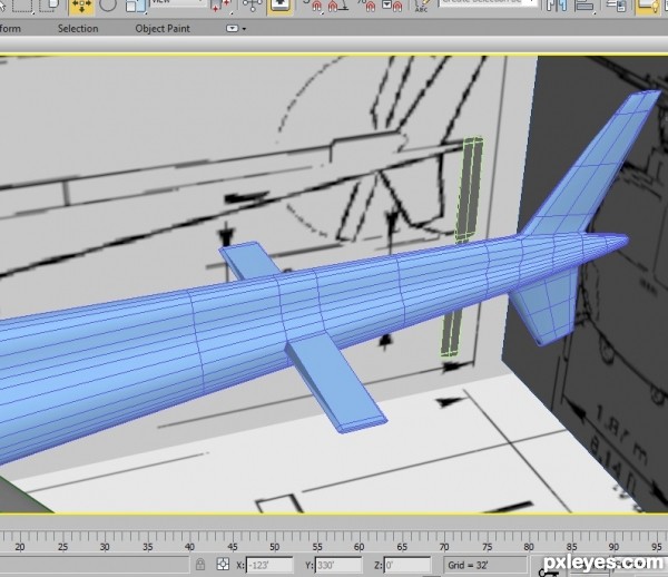
Step 55
What we should have so far is something like this. The next part is going to be the landing bars.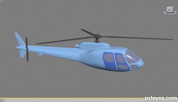
Step 56
To create the landing bars, we can use splines to draw the bars. Chose the front view and click on the shapes table, then click on line and draw an arch like this, after you have your arch check mark enable in render and enable in viewport.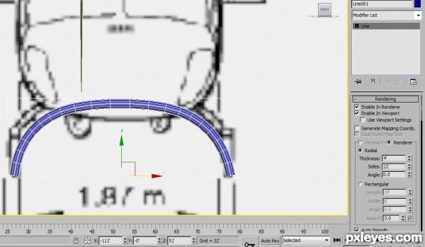
Step 57
Next move it in place in the side viewport and make a copy also as seen here.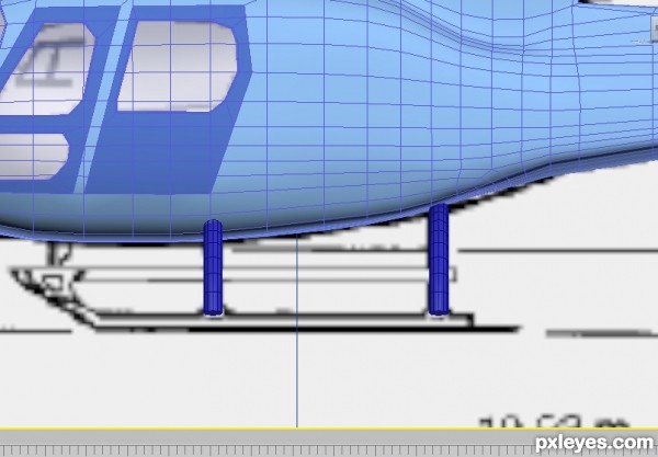
Step 58
Do the same with the bottom bar, use a spline, check mark enable in render and enable in viewport and then position it according to your blueprint. When you have all your bars in place you can then convert one of them to an editable poly object and then attach the rest.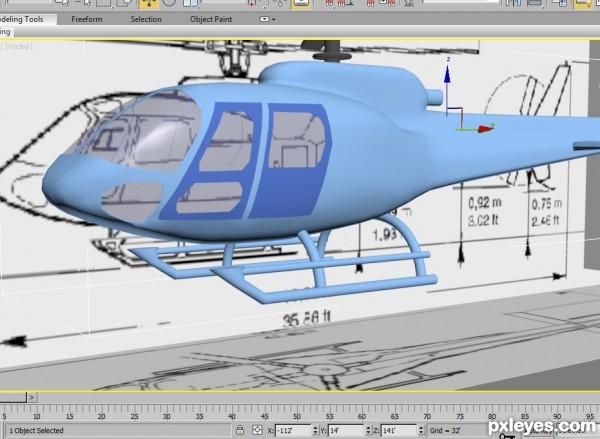
Step 59
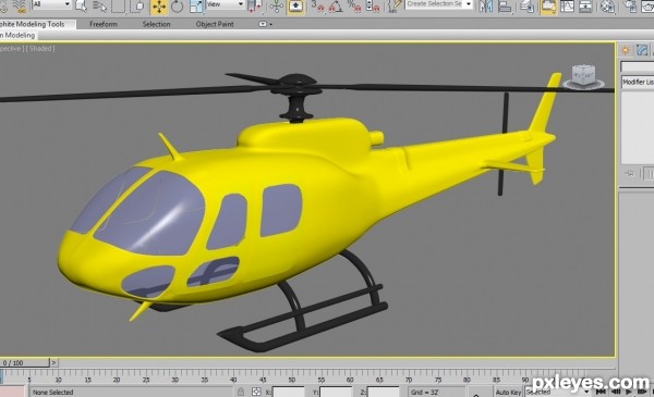
Next we can start doing more detail on the aircraft, remember to use all your reference photos of the real helicopter to look at the details. To create more details all you need to do is cut more lines, move more vertices and extrude and inset, here is what I did.I changed the color to bright yellow because this helicopter is going to be a rescue helicopter; I added a few bumps on the tail and two antennas on the front. You can add as much or as little detail as you like.
Step 60
Next we will create a quick inside with seats, cockpit and floor. First we need to create a box for the floor and then turn it to editable poly.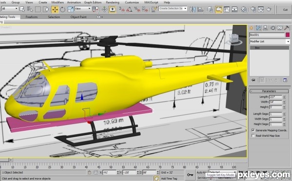
Step 61
Next let’s conform it to the helicopter by giving it more lines and moving vertices.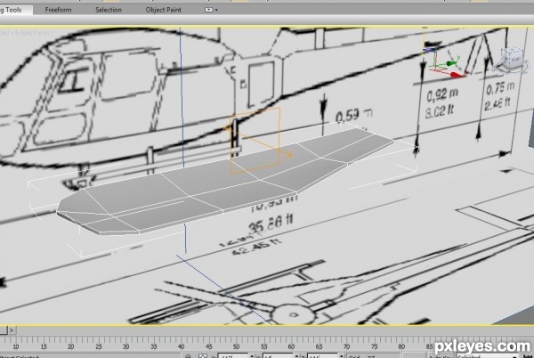
Step 62
Next we can create another box for the control panels, follow the steps in this image, the final step is to apply the mesh smooth modifier.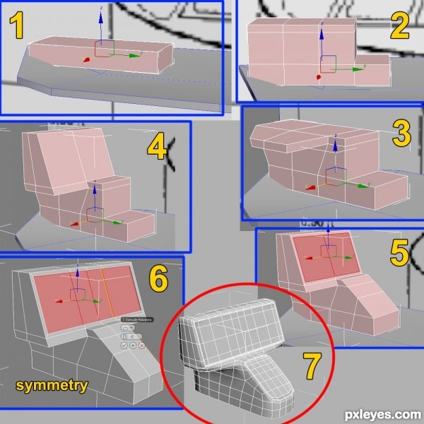
Step 63
We can do the same for our seats; follow these next steps to create your seats.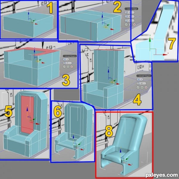
Step 64
After you have completed one seat, copy three others and position them appropriately.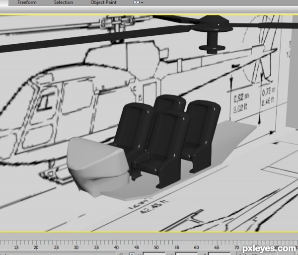
Step 65
Let’s work a little on the inside of the doors. Select both doors in Polygon mode and fully detach them.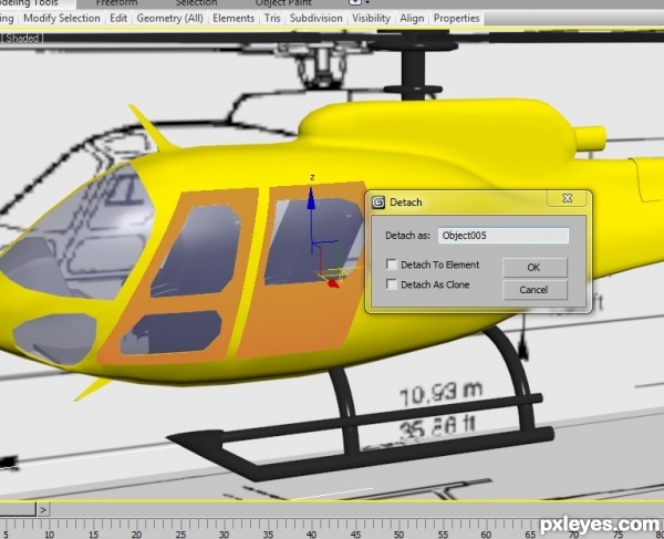
Step 66
Next we are going to add a shell modifier from your modifier stack.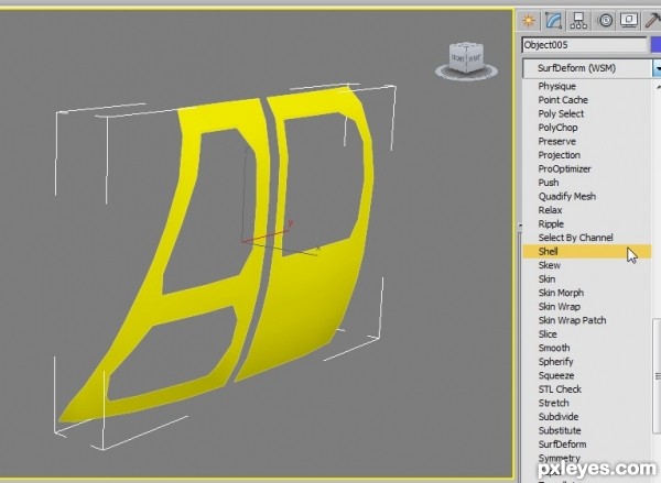
Step 67
Use an inside on 1 and an outside of 0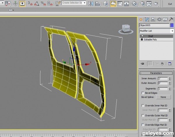
Step 68
Convert it to editable poly and then re-attach the doors.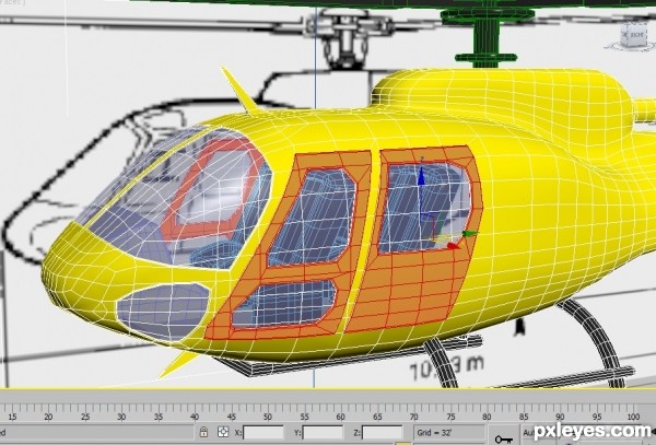
Step 69
That’s everything, all we need to do is texture our model using materials or textures and we get something like this.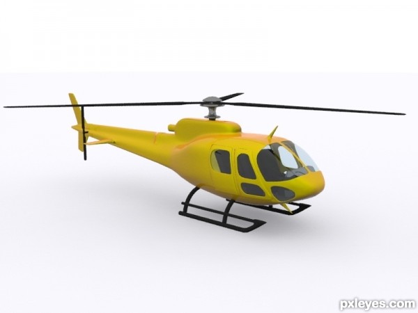
Pxleyes.com


