
Tutorial Details
- Software: Autodesk 3D Studio Max
- Difficulty: Intermediate
- Estimated Completion Time: 2 Hours
Final Product What You'll Be Creating

Additional Files/ Plugins:
Step 1
Start by creating a Line (Create > Shapes > Line) with this shape. Enter Vertex mode and select all the vertices, then Right-click and choose Bezier Corner.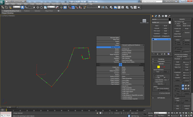
Step 2
Using the Move tool, tweak the green points at the ends of the handles for each vertex in order to get something like this.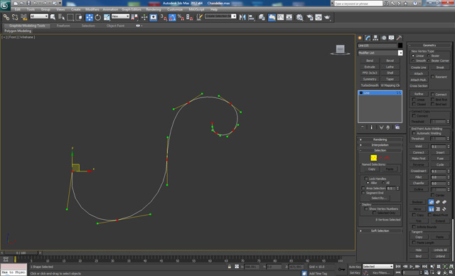
Step 3
Now go to the Rendering menu for the line, and check Enable In Viewport and set the Sides to 18. After that Convert it to Editable Poly (Right-click > Convert To > Convert To Editable Poly.)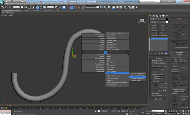
Step 4
In Polygon mode, Select and Delete the top polygon as shown. Then select the ring of edges in the last section, and add 3 new loops as shown using Connect.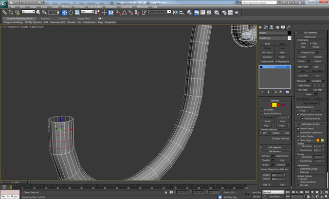
Step 5
Select and Apply an Extrude to the polygons (we got after adding the three edge loops) to get this.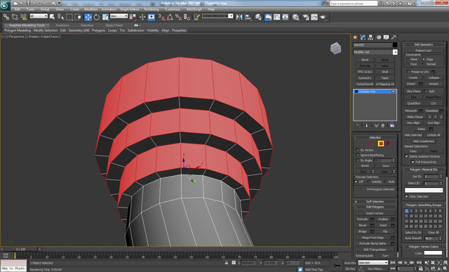
Step 6
Select the top polygons from the middle to the end. And apply an Inset and Bevel. This will be the location where we will place the cables when we finish the model.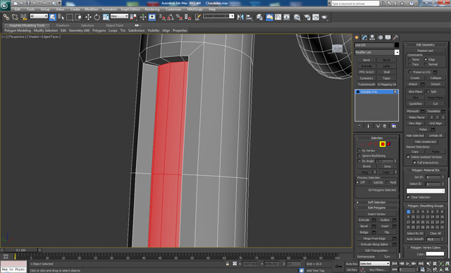
Step 7
Add 3 new edge loops to the inside of the extrude using Ring and Connect, as shown.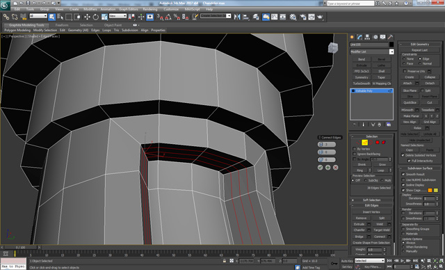
Step 8
Select the top middle polygons on the first end, and apply an Inset two times until you get this. Then repeat the same steps on the second end using the same values for the inset.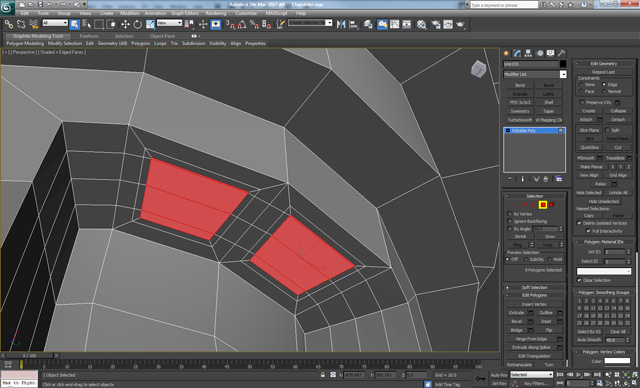
Step 9
In Edge sub-object mode. Select the outer edge loops creating by the inset, and from the Loops menu (in the Graphite Modeling Tools Ribbon) select Loop Tools and then click on Circle.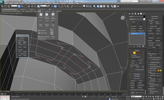
Step 10
Select the polygons in the center and click on Grow, then Delete them.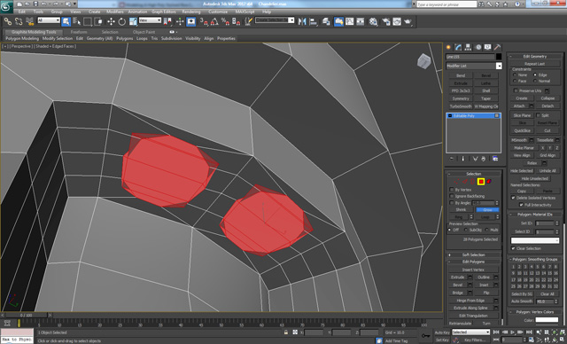
Step 11
In Border sub-object mode. Select the holes and hold down Shift and drag with the Move tool on the Z-axis. First make a short drag movement and then drag one more time in order to get a loop close to the edge, which will support the geometry once we add Turbosmooth.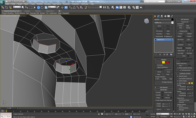
Step 12
Ring and Connect the edge rings as shown below. Apply the Connect with 2 Segments and a Pinch value of 65.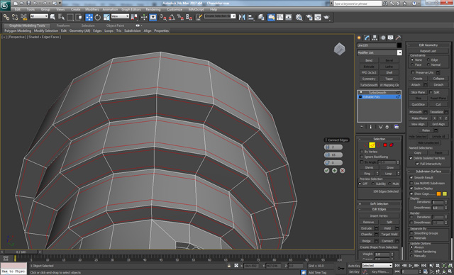
Step 13
Now Add a edge loop around the extrusion with 1 Segment and a Slide value of 90, as shown.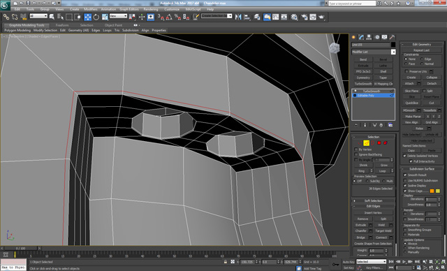
Step 14
On the other end (bottom) make the same holes and support them as well.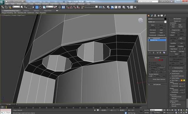
Step 15
Go to the other end of the line object and create a Sphere (Create > Geometry > Sphere) with 18 segments, Convert it to Editable Poly and Select the bottom 36 polygons.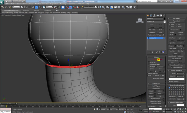
Step 16
Delete the selected polygons, and use Attach to combine the two objects together. Select the two open borders and use Bridge to create a new loop of polygons between the two elements to connect the geometry.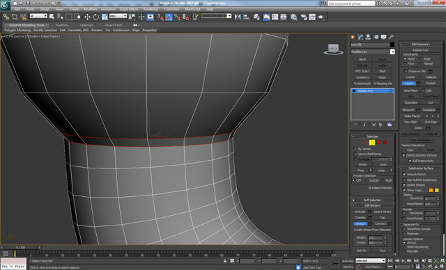
Step 17
Now back to the other end (side) of the spline object again. Select and delete the top polygons.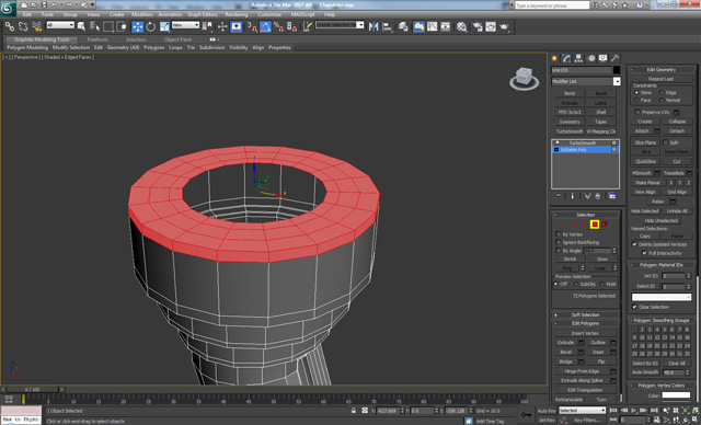
Step 18
Create a new spline (Create > Shapes > Line.) Select all vertices, Right-click and make them Bezier Corner.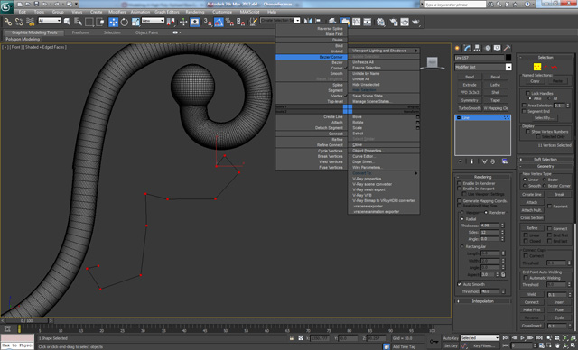
Step 19
Tweak the handles of the vertices in order to get something similar.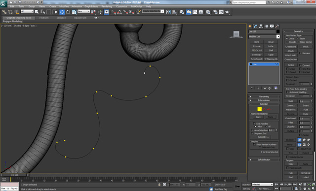
Step 20
Go to the Rendering menu again and check on ‘Enable In Viewport’ and set the Sides to 18. After that Convert it to Editable Poly, the Delete the polygons at the two ends.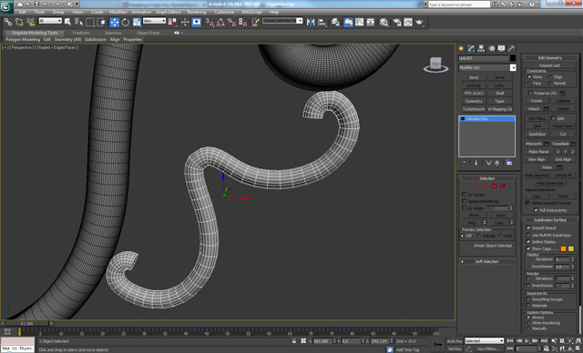
Step 21
Create two new Spheres and repeat the same actions as before, using Attach and Bridge to combine and connect them with the main object.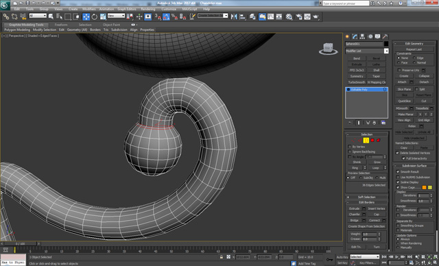
Step 22
Create a new Cylinder (Create > Geometry > Cylinder) with 18 Sides and 4 Height Segments. Convert it to Editable Poly and apply a Bevel one time on the top part, and four times on the bottom part until you get this shape.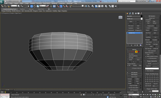
Step 23
On the top polygon apply an Inset, and on the bottom polygon apply a Bevel with a low Height value and a large Outline amount.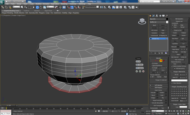
Step 24
Apply a Bevel on the top part three more times, and four more times on the bottom, until you get this shape.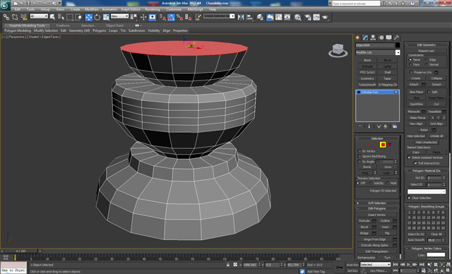
Step 25
Apply a Bevel four more times on the bottom. And then apply a Bevel to the top with a Height value of 0. Then apply Bevel once again on the top with an Outline amount of 0.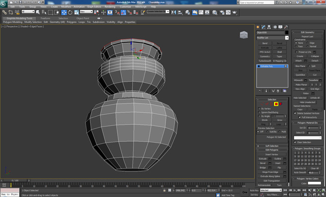
Step 26
On the top part apply the same two steps as in the previous step, but this time with a larger Height value. Apply an Inset, Extrude and Bevel on the bottom to get this result.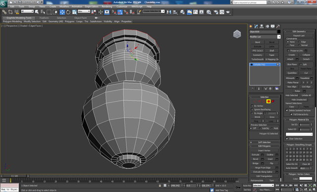
Step 27
We continue working on the bottom side by applying extrudes with negative height values. And then apply an Inset and Extrude again, but this time with a positive value and a larger Height amount. Finally apply a Bevel one more time.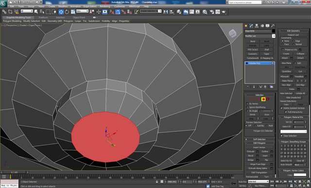
Step 28
Continue by applying a Bevel two more times with the same Height and Outline values, but for the second one make the values negative. Then continue Beveling until you get something like a deformed sphere.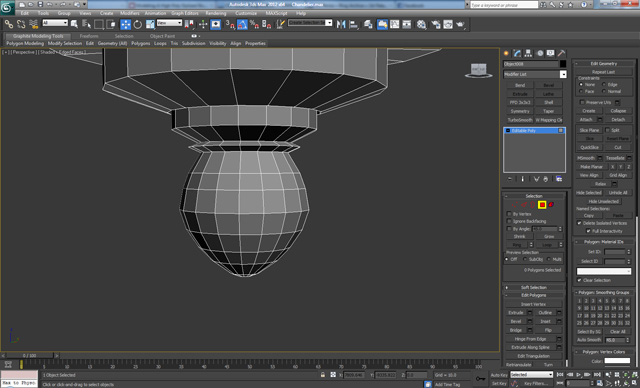
Step 29
On the top polygon we apply an Inset, Extrude and an Inset again, then Delete the polygon. The result should look like so.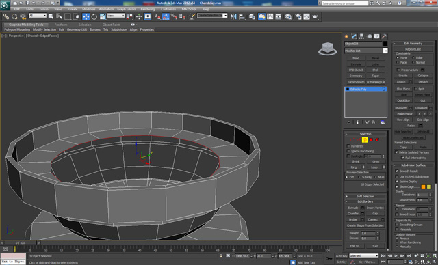
Step 30
Ring the edges and add 8 new loops on the top, and 7 on the bottom using Connect.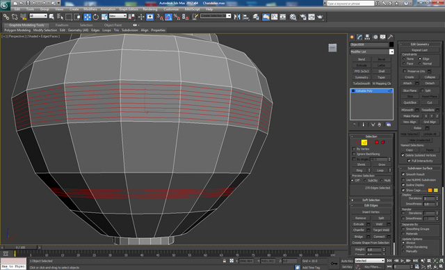
Step 31
Select the polygons between the loops and Extrude them in with a negative Height value.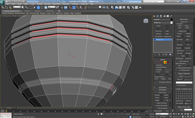
Step 32
On each ring made by the extrude add a new loop in the middle using Ring and Connect.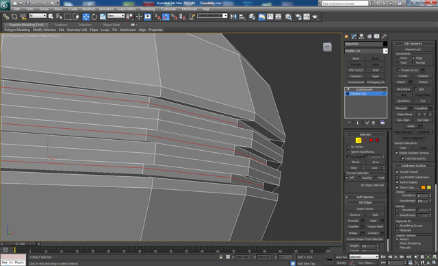
Step 33
Add some extra edge loops as shown.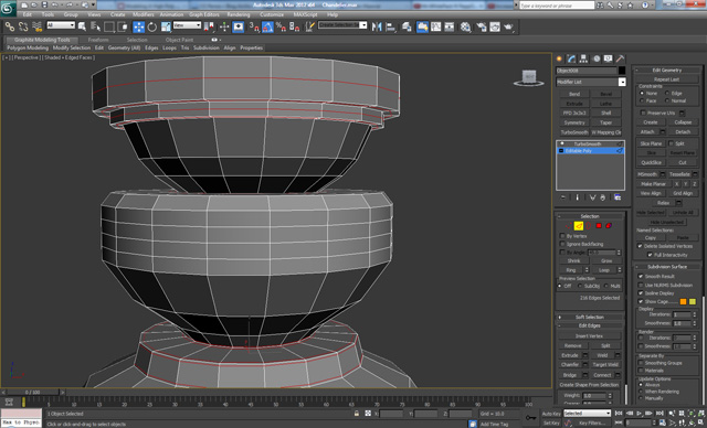
Step 34
Add more loops as shown at the bottom.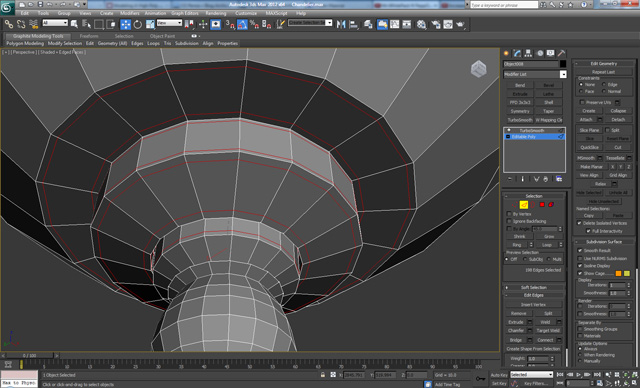
Step 35
Shift the loops on the cylinder and add one more so we have a total of four loops. Then select the polygons of each third section as shown and apply an Inset 2 times.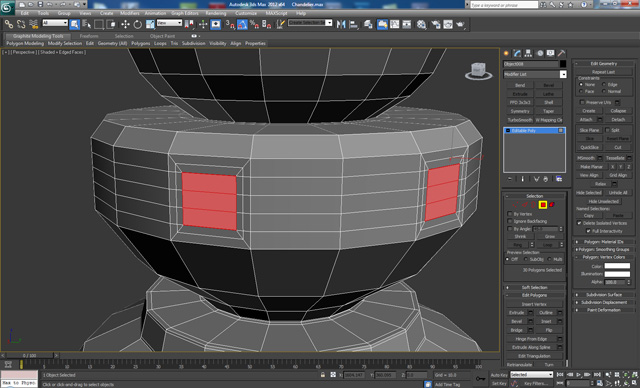
Step 36
Using Loop Tools again, add holes as we did the last time (in Step 9.)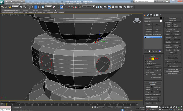
Step 37
Select the first two decorative elements and then select the eight polygons highlighted below on the main element, and Delete them.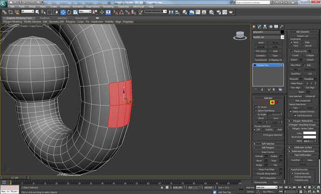
Step 38
Go to the Hierarchy panel and choose ‘Affect Pivot Only’. Move the Pivot Point to the center of the main body as shown below. Then turn Affect Pivot Only off.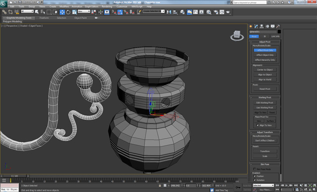
Step 39
Using the Rotate tool while holding Shift, make five more copies and Rotate them in 60 degree increments.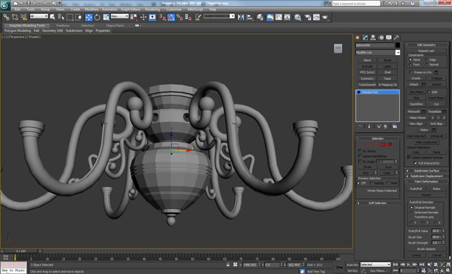
Step 40
Combine the objects together using Attach, then Select the matching borders and use the Bridge tool with 4 Segments to close the gaps. Finally apply a Turbosmooth modifier with 2 Iterations.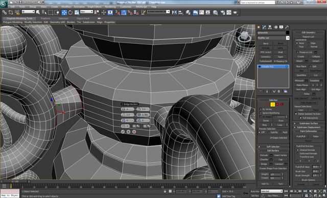
Step 41
Select the two loops shown on the bridge we just made, and Scale them like so using the Scale tool.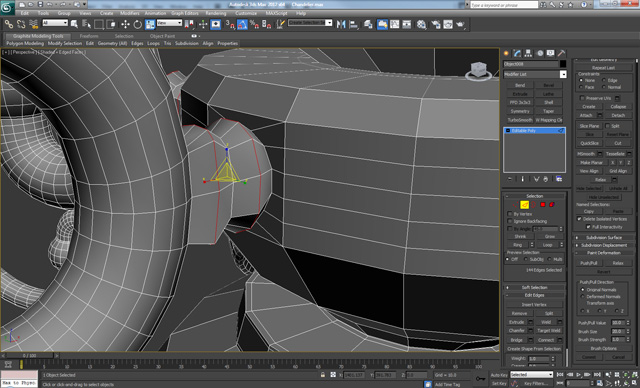
Step 42
Create a new Cylinder with 18 Sides, and 4 Height Segments. Then apply a Taper modifier and set a negative value for the Curve option.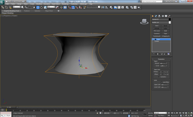
Step 43
Create a new Sphere with 18 Segments, and use the Scale tool to deform it a bit.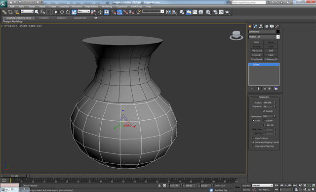
Step 44
Convert the Sphere to Editable Poly. Then select the top and bottom 36 polygons and Delete them. Delete the top and bottom polygons on the cylinder as well. Attach the objects and connect the two using Bridge.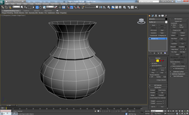
Step 45
Create another Cylinder and a Sphere and repeat the same steps. The result should look like so.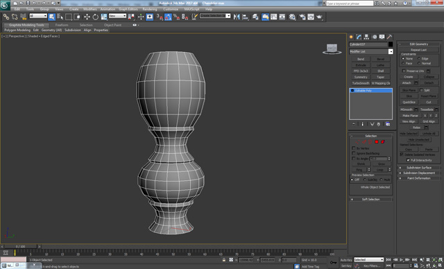
Step 46
On the top apply a Bevel 3 times. First with a negative value and the rest with positive values. Apply a Bevel to the bottom as well, with a low value in order to get this result.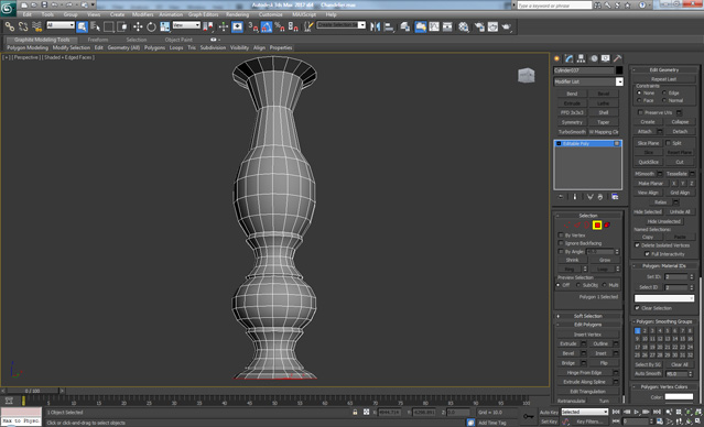
Step 47
Apply a Bevel two more times on the top part, after that Extrude and again Bevel with the same value as the second bevel we created, but this time use a negative Outline.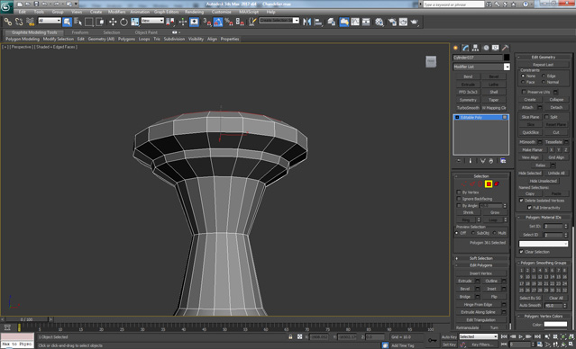
Step 48
Continue by adding a Bevel two more times with a positive Outline. Then add a bevel with a 0 Height value and then extrude. Again apply a Bevel with 0 Height and a slightly bigger outline, finally Extrude again.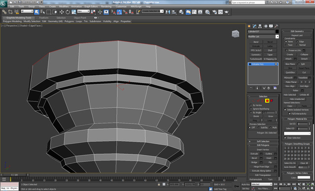
Step 49
Apply an Inset and then Extrude with a negative value. Again Inset and apply a Bevel with the same Height as the extrude, but this time with a positive Height and a negative Outline.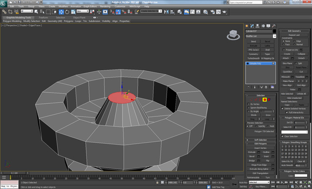
Step 50
Apply an Inset on the top polygon, and then add two new loops on each edge as shown below.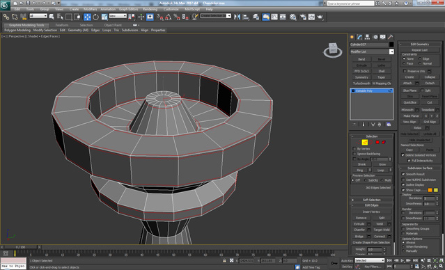
Step 51
Add loops where the connections are between the spheres and cylinders.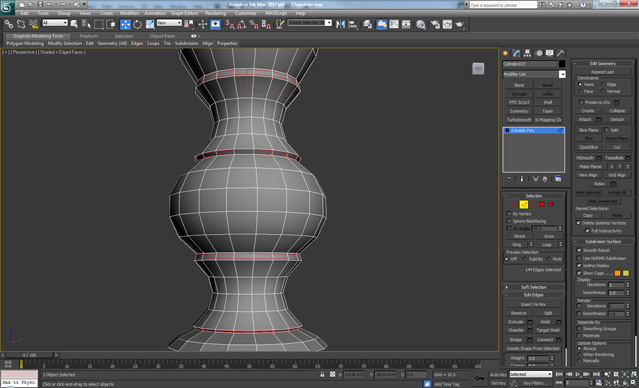
Step 52
On the top Create two new loops around the inside of the center and then using the Loop Tools make a hole on each side. Create a Torus object (Create > Geometry > Torus) with 8 sides and combine it to the object using Attach. Finally Delete the bottom 6 polygons of the torus and connect the elements together using Bridge, set the segments to 2.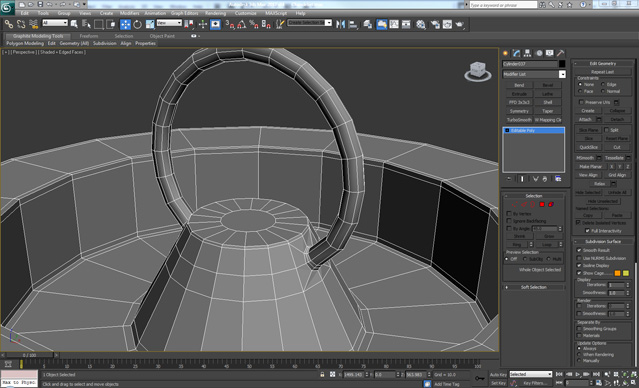
Step 53
On the center polygon apply an Inset and then Extrude with a negative Height value, and then Delete the center polygon. On the edge apply a Chamfer and set the segments to 2. Finally apply a Turbosmooth modifier – Iterations 2.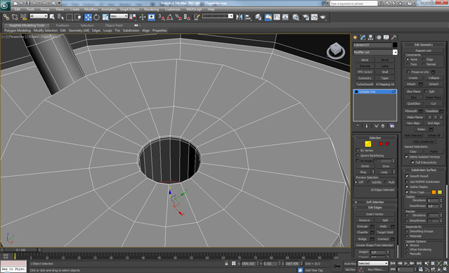
Step 54
Create a new Cylinder with 2 Height Segments and Convert it to Editable Poly. Then on the bottom polygon, apply an Inset two times, then Extrude and finally Inset again.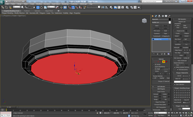
Step 55
Apply a Bevel two more times, and then an Inset two times as shown below.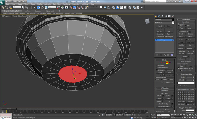
Step 56
On the top, we apply an Inset and then Delete the polygon.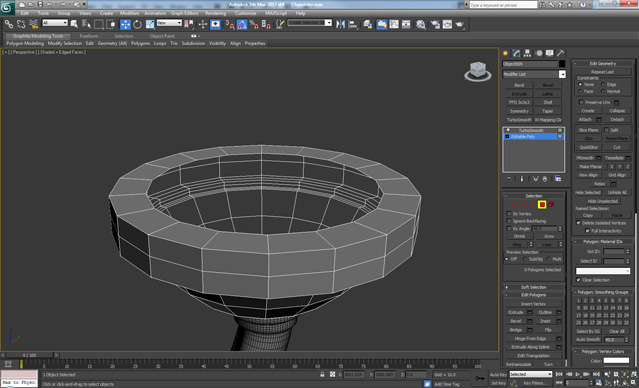
Step 57
Create a new Cylinder, Convert it to Editable Poly and Scale down the bottom polygon, then Bevel it four times.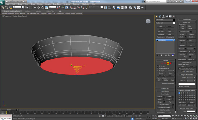
Step 58
Apply a Bevel four more times in order to get a rounded shape like this.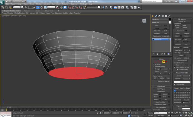
Step 59
Now Bevel again five more times in order to get this shape.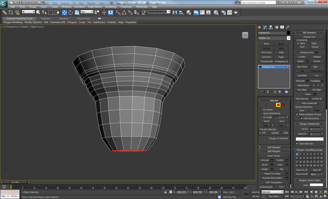
Step 60
Select the groups of polygons highlighted below, and apply a Bevel.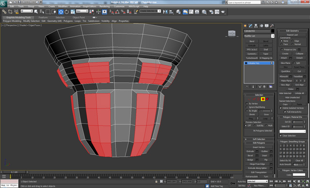
Step 61
Delete the bottom polygons, and add new edge loops as shown below.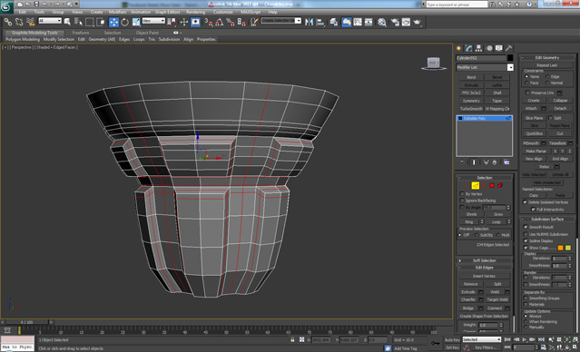
Step 62
On the top polygon we first apply an Inset, and then using Bevel we create a shape similar to the outside of the element in order to give it thickness.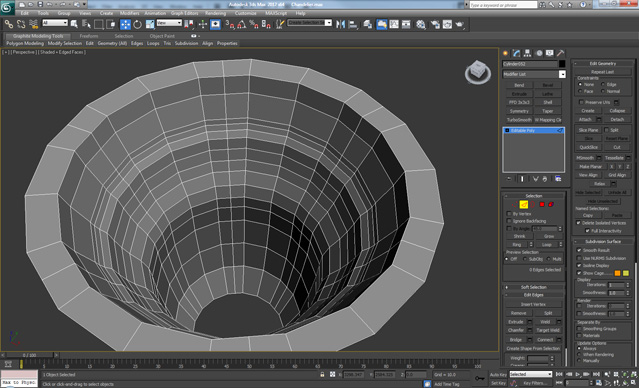
Step 63
Close to the edges, add loops and finally apply Turbosmooth – Iterations 2.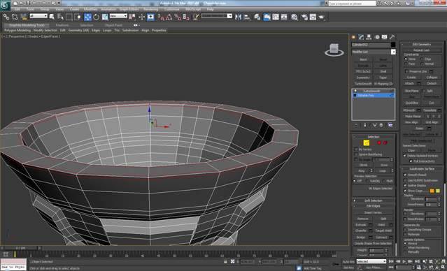
Step 64
Create a new spline with a curved shape, and then from the Rendering menu choose Rectangular and check on ‘Enable In Viewport’.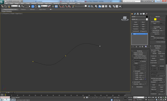
Step 65
Convert it to Editable Poly and add loops close to the edges as shown, and then Delete the two side polygons.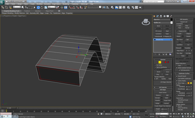
Step 66
Apply a Turbosmooth to the element and using the Rotate and Move tools position it like so. Go to the Hierarchy Panel and click on ‘Affect Pivot Only’ and set the pivot point to the center of the big element in order to rotate the copies of this element around the main element.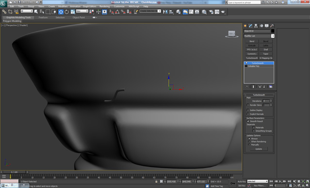
Step 67
Go to the Tools menu and click on Array… choose Rotate > Totals and enter 360, and set the Array Dimensions 1D to 70 and click OK.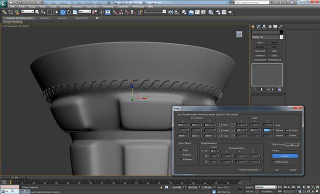
Step 68
Create a slightly curved Line and apply the same settings as on the previous one.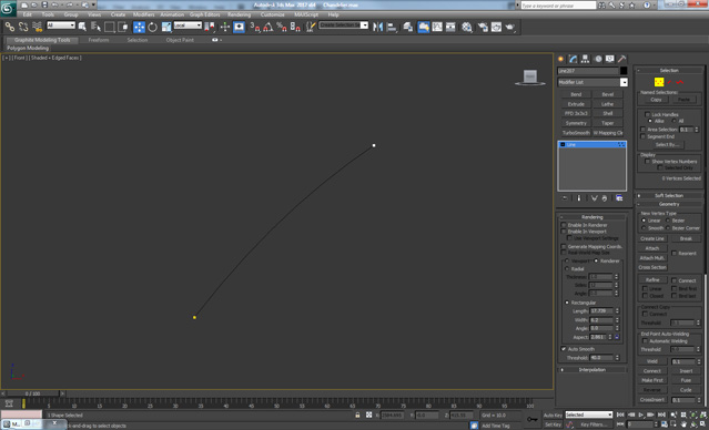
Step 69
As in the previous steps, Convert the line to Editable Poly and add loops close to the edges. Apply smooth, and using the Array function add 70 copies.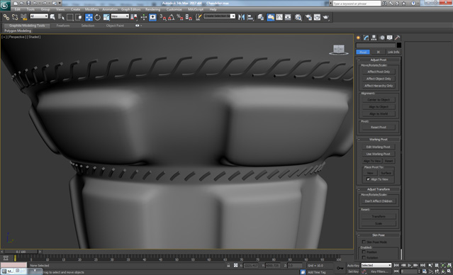
Step 70
Now Create a new spline which has the profile of light bulb.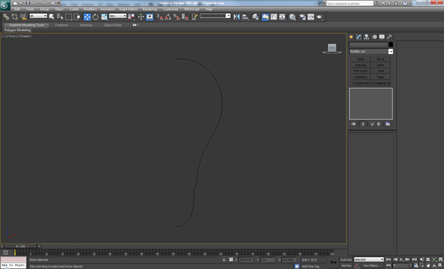
Step 71
Add a Lathe modifier and check on ‘Weld Core’, "Flip Normals’ and from the Align settings, click ‘Min’.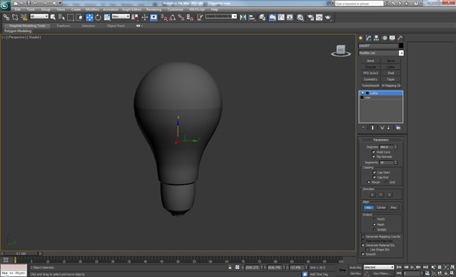
Step 72
Add a Turbosmooth – Iterations 1 and place the light bulb in the correct position as shown below.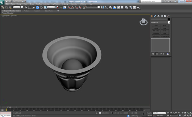
Step 73
Group all the elements plus the light bulb (Group > Group), and from the Hierarchy menu click ‘Affect Pivot Only’ and center the Pivot to the center of the main body. Finally make five copies and rotate them like so.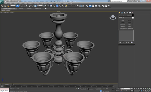
Step 74
Create two new Lines which will be our cables. Check ‘Enable in Viewport’ and give them a medium thickness and then convert them to Editable Poly. And as we did before, make five copies and rotate them around, one for each arm.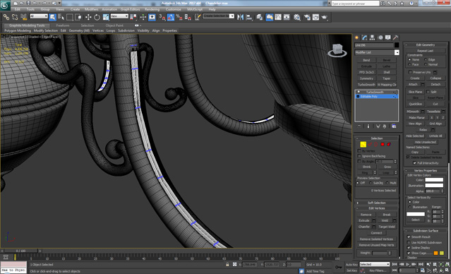
Step 75
Create a new Cylinder and Convert it to Editable Poly. Delete the top polygon and on the bottom one, apply a Bevel two times, Inset and then bevel, Extrude, and Bevel again with the same value as the bevel before the extrude. The result should be like this.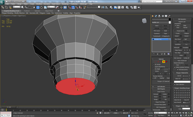
Step 76
We continue by doing an Inset, Bevel, Extrude, and Inset. Extrude again with a high value for the Height and then Inset again, and finally Extrude with a negative Height.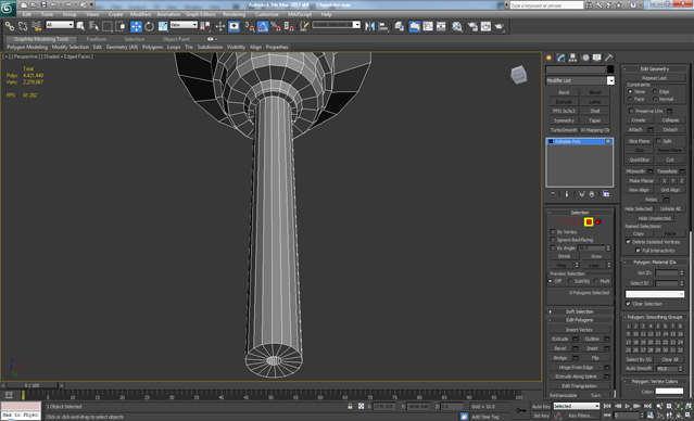
Step 77
Add some additional edge loops using Ring and Connect as shown.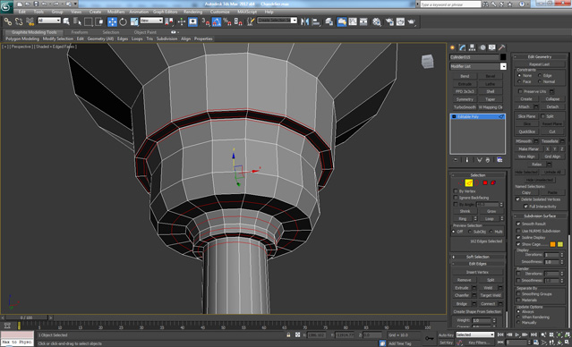
Step 78
Add additional edge loops at the bottom as shown, and make a hole on the side using the techniques previously covered.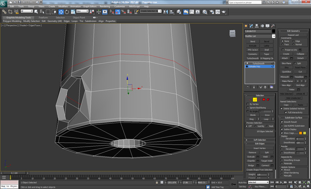
Step 79
Create a new Torus with 12 Sides and 24 Segments and Convert it to Editable Poly. Delete the bottom half and while holding Shift, drag downwards to create something like this.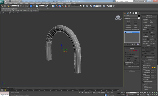
Step 80
Apply a Symmetry modifier, set the Mirror Axis to Y, and then Convert the object to Editable Poly.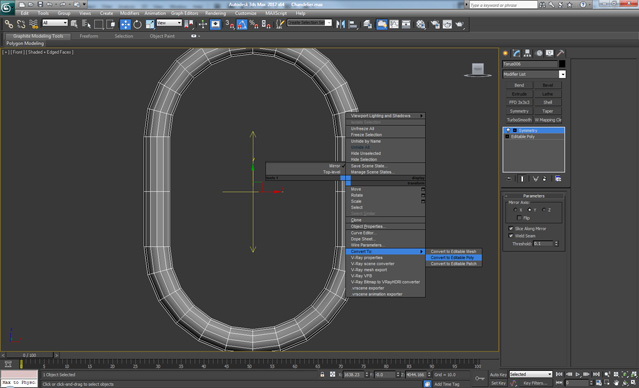
Step 81
Add two new edge loops on one side, and Delete the polygons between the new loops. Then select the two borders and hit the Cap button, finally apply a Chamfer to the edges.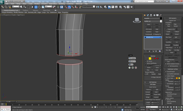
Step 82
Add a Turbosmooth modifier and make a few copies of the element in order to get something like a chain. After that make a new Line that goes in the holes, this will be our cable.
Step 83
Finally go back to the top element and select the top border. Using Shift + drag, move it upwards. The first time make a small move, and for the second make a larger one in order to get a supporting edge from the first move. This will complete our Chandelier model.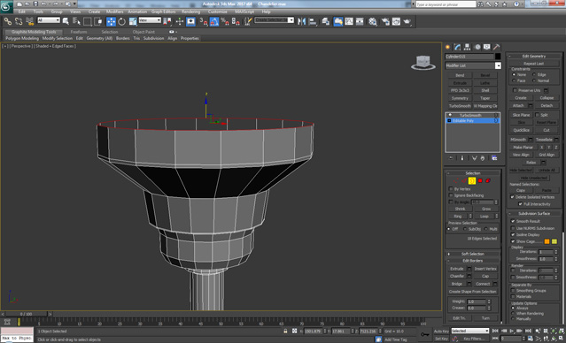
Source : Cgtuts+ ..


No comments:
Post a Comment