by Didik Wijaya
 After texturing Optimus Prime, I will continue to explain the next lesson, skinning and rigging Transformers Optimus Prime robot. I will use Bones and IK (Inverse Kinematics) to rig the robot. The process is much similar to my previous tutorial, Rigging Mechanical Robot. But this Optimus Prime is more complicated, so I use a lot of modifications here.
1. First, you need textured Optimus Prime 3D model. You can download here. After you download, open 3ds max file (optimusprime_texturing_finish.max).
Freeze all objects if you want (Freeze option is available in Display tab). Now, create Bones. Go to Create>Systems. Click Bones button. In Bone Parameters rollout, use Width=1 and Height=1 to use thinner bones. In Left viewport, click two times to create body bone (1-2), after that right click to finish creating bones. You will have one small bones at the end of bones hierarchy. You can delete this bone.Repeat the process to create neck and head bones. Make sure all bones are in the middle of objects. Move them if necessary.
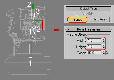
2. Next, I will use IK (Inverse Kinematics) to create bones for leg. IK is a system that enable you to move whole bones at once. To understand IK, look at your own leg. You have upper leg, lower leg and foot. If you are not using IK, that means Forward Kinematics, you rotate upper leg, then rotate lower leg, and last rotate the foot. In IK, you just need to move the foot and other part of leg will adjust itself.
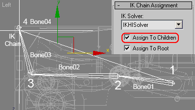
Create bones, this time activate Assign To Children. Other option Assign To Root will also active. Click four times in Left viewport to create bones like image below. Right click to finish. You'll see (+) object before the last bone. This is called IKChain or Goal . Try to move this goal and you'll understand what IK is all about. Press Ctrl+Z to undo.
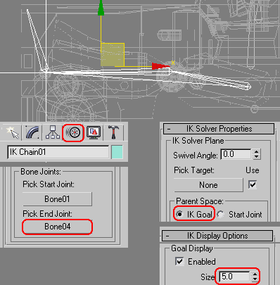
3. I need to move Goal to the heel position. Most common, people use IK legs from upper leg to lower leg, and moving or rotating the foot manually. Make sure Goal is selected, and go to Motion tab. In IK Solver rollout, click button under Pick End Joint. And click Bone03. Goal will move into new position, but bones position will also move. Move Goal into heel position and all position will be fixed. Delete small end bone.
In IK Solver Properties rollout, activate Parent Space=IK Goal. In IK Display Options, set Goal Display Size to 5. This will make IK Goal smaller.
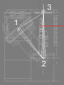
4. Creating IK for arms is almost the same with legs. Create bones with IK in Left viewport (from upper upper arm to wrist). This time don't delete the small bone. Look at image below for reference.
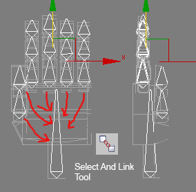
5. Zoom in hands area. Create bones for palm and fingers This time without IK. Adjust bones position in Left viewport. Next, link finger bone to the palm bone. Click Select And Link tool. Select bone closest to palm bone. Click this bone and drag to palm bone until cursor is change and release. White flash will confirm that they're linked. You have to do this five times. In image below, read arrows show the link connections.
6. Create three bones like image below (without IK)

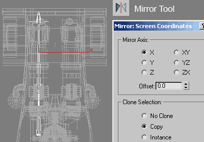
7. In Top viewport, make sure all bones are in positions (left side) So far, you created bones for the left side. You need to make bones for other side. Select all left side bones, Use Mirror Tool (Tools>Mirror) with Copy option active.
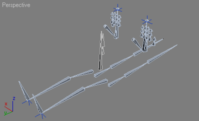
8. When finished, image below show finished bones.
1. Before we go to the skinning process, we need to modify the Pivot Point location for many objects. Not all objects is controlled by bones. I am not using bones for each objects to reduce the complexity controlling the bones later.
For example, select object named "shoulder side left". Go to Hierarchy tab. Click Affect Pivot Only, and move Pivot Point at the center of "pipe" object. When finished, turn off Affect Pivot Only. This new Pivot Point location is used as rotational axis later
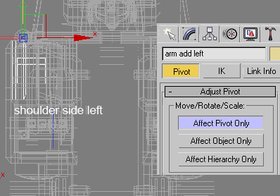
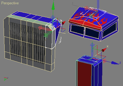
2. There are many objects that needs to be modified its Pivot Point location. Image below shows just a few examples. I am not explaning all objects, because there are too many, and basically the process is the same.
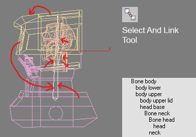
3. Next, the skinning process. Usually we need skinning process when using bones. But fortunately we work with mechanical object. They are all stiff, un-deformed object. So, you just need to link each body part to corresponding bone. For example head object linked to head bone, body object linked to body/pelvis bone, and so on. You may link object to other object. For example "body upper lid" to "body upper". Image below shows example of linking objects in body and head. Again, I don't explain all linking process. There are too many objects and basically the process is the same. I suggest that you download the finished 3D model and learn the hierarchy by yourself.
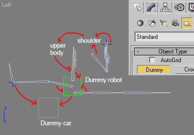
4. After all objects is connected to bone or other object, now we need to controll all bones. In Command Panel, go to Create>Helpers. Click Dummy button. Click and drag in Top viewport to create dummy object. Position dummy in pelvis area. Actualy creating dummy is optional. I use dummy for easy selection. When all geometry and bones visible in viewport, it's hard to see and select body/pelvis bone. It's easier for me to select dummy instead. Create other dummy. So you have 2 dummies, one for controlling pelvis (Dummy robot), and the other for controlling whole car (Dummy car).
Next link bones and IK chains to dummy. Image below shows the linking hierarchy.
Finished rigged Optimus Prime can be downloaded here (optimusprime_rigging_finish.max). Try to move the IK chain, and dummy. Ctrl+Z to undo
Next is animating Optimus Prime!

if i near u i learn more and more i love 3d max much more
ReplyDeletethank you , i hope you get all your hope .
ReplyDelete