by Didik Wijaya
 This tutorial is the first section of Transformers Animation Using 3ds Max. In this tutorial you will learn to model a Peterbilt Truck. Optimus Prime, leader of Autobot is able to transform from robot to this huge truck, or vice versa. As always, I will show you how to model Peterbilt Truck in detailed step by step tutorial. If you have followed all my previous tutorial, I am sure you can follow this tutorial easily.
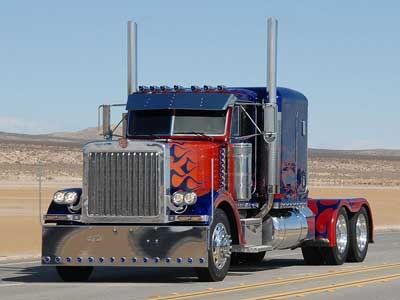
This is the Optimus Prime Peterbilt Truck shown in Transformers The Movie.
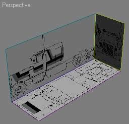
1. First, we need a blueprint. I looked everywhere on the net, but the only images I could find is the Peterbilt 379, a little bit different model from Optimus Prime's. But anyway, I still can use the image. I already prepared blueprint like image below. You can download required file here. Open file "modeling_truck_start.max". If you want to know how to create blueprint for modeling like this, read here.
2. First, let's create the cab, where the driver is seated. In Top viewport, create a box with 4 x 2 x 1 segments. Place this box the middle of blueprint. Apply with transparent material, so you can see the blueprint behind. Right click and choose Convert to>Convert to Editable Poly. Go to Modify tab. Activate Vertex selection. Move vertices like image below.
3. (1) Change to Polygon selection. Select 6 polygons at the bottom of box. In Edit Polygons rollout, Click Extrude, then click and drag to extrude selected polygons a little bit. (2) Reduce selection until only 4 polygons are selected. Extrude again. (3). Change to Vertex selection. In Left viewport, move vertices like image below. Original position shown in red color. New position is in yellow color.
4. (1) Select one vertex. Move this vertex to new position (yellow color). (2) Activate Polygon selection. Select two polygons on top of the box. (3) Extrude selected polygons twice. Modify vertice position like image below.
5. Select 2 polygons on top of cab. Extrude. In Left viewport, modify vertices position to create sharp cab roof.
6. Activate Edge selection. Select 4 edges at the hood area. In Edit Edges rollout, click Chamfer button. Click and drag at selected edges to smooth the edges. Then activate Vertex selection. In Edit Vertices rollout, click Target Weld. Then click one vertex and drag to another vertex. Repeat this procedure to another vertex. Tips: activate 3D snap to precisely selecting vertex to get welded.
7. To create windows, activate Polygon selection. Select 4 polygons where you want to create window. Click Inset Settings button. In opened window, activate By Polygons. Adjust Inset Amount. Then use Extrude with negative value to make selected polygons go inward.
Modify vertices at the middle of front window, to make thinner window separator.
5. When finished, turn off all sub object selection. Here's the finished cab.
by Didik Wijaya
In Part 1 tutorial, you have created a cab, where the driver is seated. Now in this tutorial you will add several details to the Peterbilt truck.
1. In Top viewport create a box with 2 segments. Place it in the middle, as we will use it as a body. Convert to Editable Poly. Activate Vertex selection and move several vertices at the back of the truck.
2. Create box again, with 1 x 1 x 1 segments. Place it behind the cab. Convert into Editable Poly. Activate Edge selection. In Left viewport, select all edges, except edges at the bottom. In Edit Edges rollout, click Chamfer button. Click and drag to smooth selected edges.
3. Create a box and oil tank (this object is available as extended primitive). Place them based on blueprint. I leave it you to create them by yourself. I am sure you'll find no problem here.
4. Next, in Left viewport create a tube like image below. After that, clone tube twice and move them at rear tires.
5. Back to the tube at front tire. Convert into Editable Poly. Activate Polygon selection. In Left viewport, select several polygons like image below. Delete them.
Change into Border selection. Select borders like right image below. In Edit Borders rollout click Cap button to close the holes.
6. Focus on rear tires. I will make objects different from blueprint. Select one tube. Convert into Editable Poly. Go to Modify tab. In Edit Geometry rollout, click Attach button. Click another tube. They will be combined into single object. Activate Polygon selection. Select polygons like image below. Delete these polygons.
Change into Border selection. Select borders number 1 and 2. Use Cap to fill holes. Select borders number 3 and 4. Click Bridge button to connect them.
7. When finished, you'll have something like image below.
part 3
by Didik Wijaya
In this tutorial, you will add more details to the Optimus Prime Peterbilt truck. This time you will add tubular pipe at the side of the truck
1. First, add simple object below the cab. This is where a driver step on to get into the cab. I created a simple box with two segments in Left viewport. Convert into Editable Poly. Move the middle vertices down. Select one polygon and extrude. It's finished.
2. In Top viewport, create one oil tank and one cylinder.
3. Focus on the cylinder. Convert into Editable Poly. Activate Polygon selection. Select two polygons at top and bottom. Use Inset then Extrude like image below.
4. In Left viewport, move vertices at top of cylinder to lengthen the pipe. De-activate sub object selection. In Edit Geometry rollout, click Slice Plane button. Rotate slice plane (yellow line) like image below, then click Slice button. Active polygon selection, select upper sliced polygons, and delete.
5. De-activate all sub-object selection. Next, modify the bottom part of cylinder. In Back viewport, draw 2 lines like image below. Go to Modify tab. Activate Vertex selection. Select one vertex at corner, and in Geometry rollout increase Fillet value.
Tips: To draw line, hold Shift to draw straight line. Right click to finish drawing lines.
6. Select cylinder. Activate Polygon selection. Select one polygon at the bottom of cylinder. In Edit Polygons rollout, click Extrude Along Spline Settings button. In opened window, click Pick Spline and click previously created spline. Click OK.
7. With round corner polygons in cylinder still selected, hold Shift and move to another location. In opened dialog box Choose Clone to Object. You will create new object. And position this new object near the vertical oil tank.
part 4
by Didik Wijaya
Detail, detail and detail. I hope you won't get boredto add more details, because detailing will make object looks more convinving. This time you will add side mirror and other details.
1. In the back of box behind the cab, there are some kind of handles. You can create this handle by creating a 3 segment box and modify its vertices.
2. To create side mirror, first create a long 4 segments box in Top viewport. Then, modify its vertices based on blueprint. When finished, select all polygons and in Back viewport, clone these selected polygon (hold Shift and move down). Modify its vertices a little bit. Then you can create the mirror using simple modified box.
3. Select side mirror holder. Select one polygon like image below, and extrude. Then in Back viewport you can move selected polygon above to create diagonal pole.
4. To create front lamp, just use a box.
by Didik Wijaya
This is the final part on modeling Peterbilt truck tutorial. You will add tires and rims.
1. In Left viewport, create a tube to be used as front tire. Convert into Editable Poly. Activate Edge selection.Select all loop edges (select edges and click Loop in Selection rollout). Use Chamfer to smooth selected edges.
Next, in Left viewport, create an oil tank to be used as rim. Convert into Editable Poly. Activate Polygon selection. Delete un-necessary polygons.
2. Clone tire from front to the rear.
3. Rim for rear tire is a little bit different from the front. In Left viewport, create a cylinder like image below. Convert into Editable Poly. Activate Polygon selection. Select one polygon, then apply Inset, Extrude and Bevel until you get something similar to image below. Clone this rim to adjacent tire
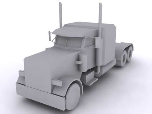
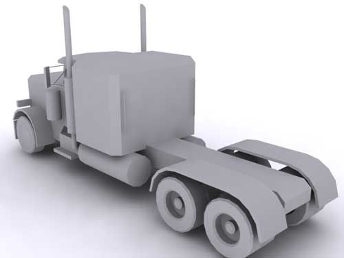
4. Final step, select all object except cab, big box and body. Use Mirror Tool to create mirrored selected object. Peterbilt truck is finished.
5. Image below shows finished Peterbilt Truck. Next section: Modify this truck to create Optimus Prime body parts.


This is awesome mate, well done and thanks :)
ReplyDeleteHello.. I use Vitual Gibbs and wanted to know if you had a DXF file or IGES file of this.. This is awsome!!!
ReplyDeleteDimensions: Modeling Peterbilt Truck >>>>> Download Now
ReplyDelete>>>>> Download Full
Dimensions: Modeling Peterbilt Truck >>>>> Download LINK
>>>>> Download Now
Dimensions: Modeling Peterbilt Truck >>>>> Download Full
>>>>> Download LINK